This started because my variac began dying.
They are used to control a the heat level in old style heating mantles seen
in organic chemistry labs.
My variac got to the point where it would only work at 60% and up, meaning
I couldn't keep things at low heat levels. The idea to use a long period
controller came from my kiln controller, which turns my kiln on and off,
within a fixed cycle time but variable duty cycle (the on portion of the cycle
period). You can think of it as someone standing around and turning the power
on and off, with longer on/shorter off time when you want it on high, or
shorter on/longer off, when you want it not as high. This is often referred to
as pulse-width
modulation or PWM for short.
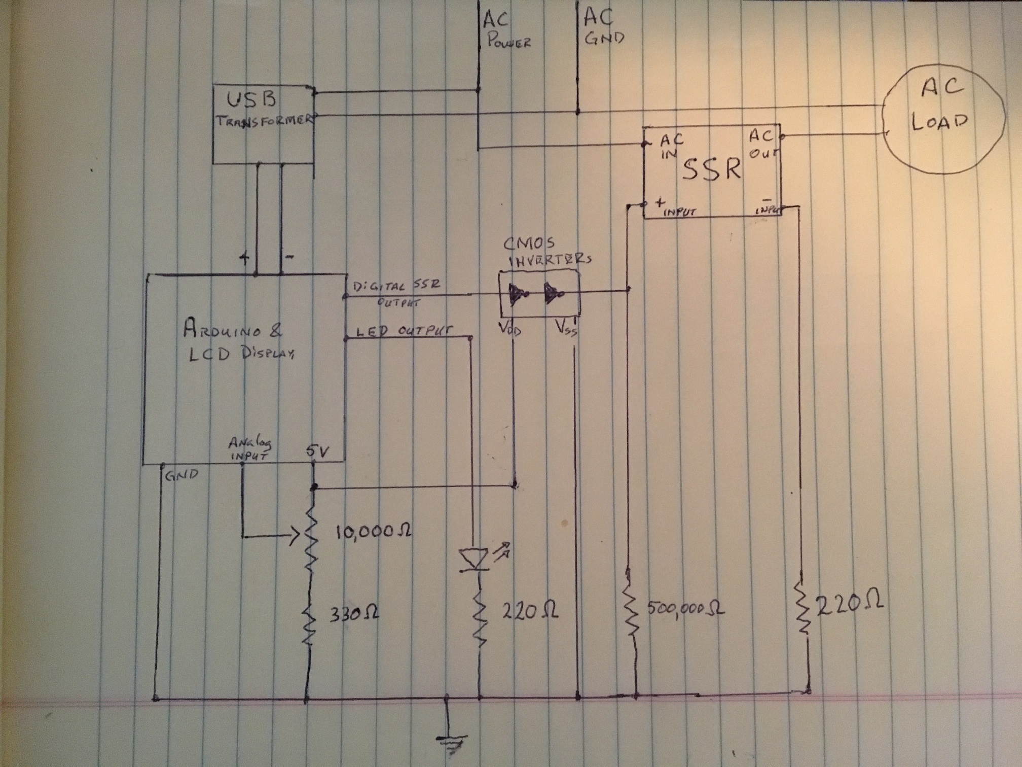
The idea was to use an Arduino (sort of a small,
cheap microcomputer on a board) to control an solid state
relay (SSR) which would control turning the AC power on and off. Arduino's can be set up to use a potentiometer as an input device, to allow the user to alter the percent of time the power is to be on, within the cycle period.
Arduino's include a PWM function, but the cycle period is extremely short.
Short enough I had concerns the SSR could be quickly degraded if operated
at frequency. Hence why I'm doing it as a long cycle PWM.
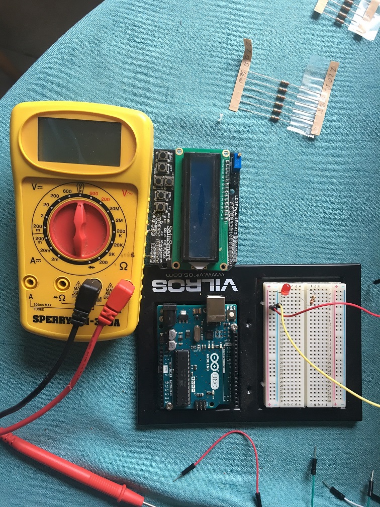
List of components
Arduino and LCD separate
|
|
- $ 2.44 ea
- $15.99
- $10.99
- $12.97
- $ 2.25
- $ 2.19
- $ 2.09
- $ 4.02
- $ 2.69
- $ 4.99
- $ 9.95
- ~$10.00
Approximate cost $88
|
Procedure
Before getting into the process full steam, what follows is the intended
process, containing only some of the mistakes and rework that happened, time and time
again as I went through this. I'll include a section on some of the many pitfalls I encountered.
-
Before I started programming, I grabbed a 10K ohm potentiometer (POT) and ran it
between the 5 volt connection and the ground, on the Arduino, then wired the center pole
to the analog input. This means the voltage showing at the analog input would
range between 0 and 5 volts, depending on where you dialed the POT to.
-
Then I wired an LED (with 220 ohm current limiting resistor) from one of
the digital outputs, then to ground.
- Arduino's have to programmed, being they are basically little
minicomputers. Fortunately I already had some Arduino code I wrote to display
to the LCD.
First a note about how an Arduino program executes. There is a setup
section and a loop section. The setup section is used to initialize
everything, then the loop section keeps looping through it's to continously
perform what you want.
The following describes what needed to be executed each pass through the loop
-
I wrote a simple program reading the voltage off the analog input pin I'd attached the POT's center pole to.
-
Once the voltage was read, I divided the voltage by 5 volts to get a
percentage. That percent I use to determine what percent the duty cycle will
be of the full cycle time. aka the time it will be on.
-
Once the percentage of the cycle time is computed it would test to see
if the end of that portion of time was finished. Assuming the percentage
wasn't zero or 100%, it'd toggle the on/off state and set a new target time to
change state again.
If the percentage was either 0 or 100%, the new target portion was set, but
the on/off state was ensured to be on or off respective to 0 or 100%,
respectively.
-
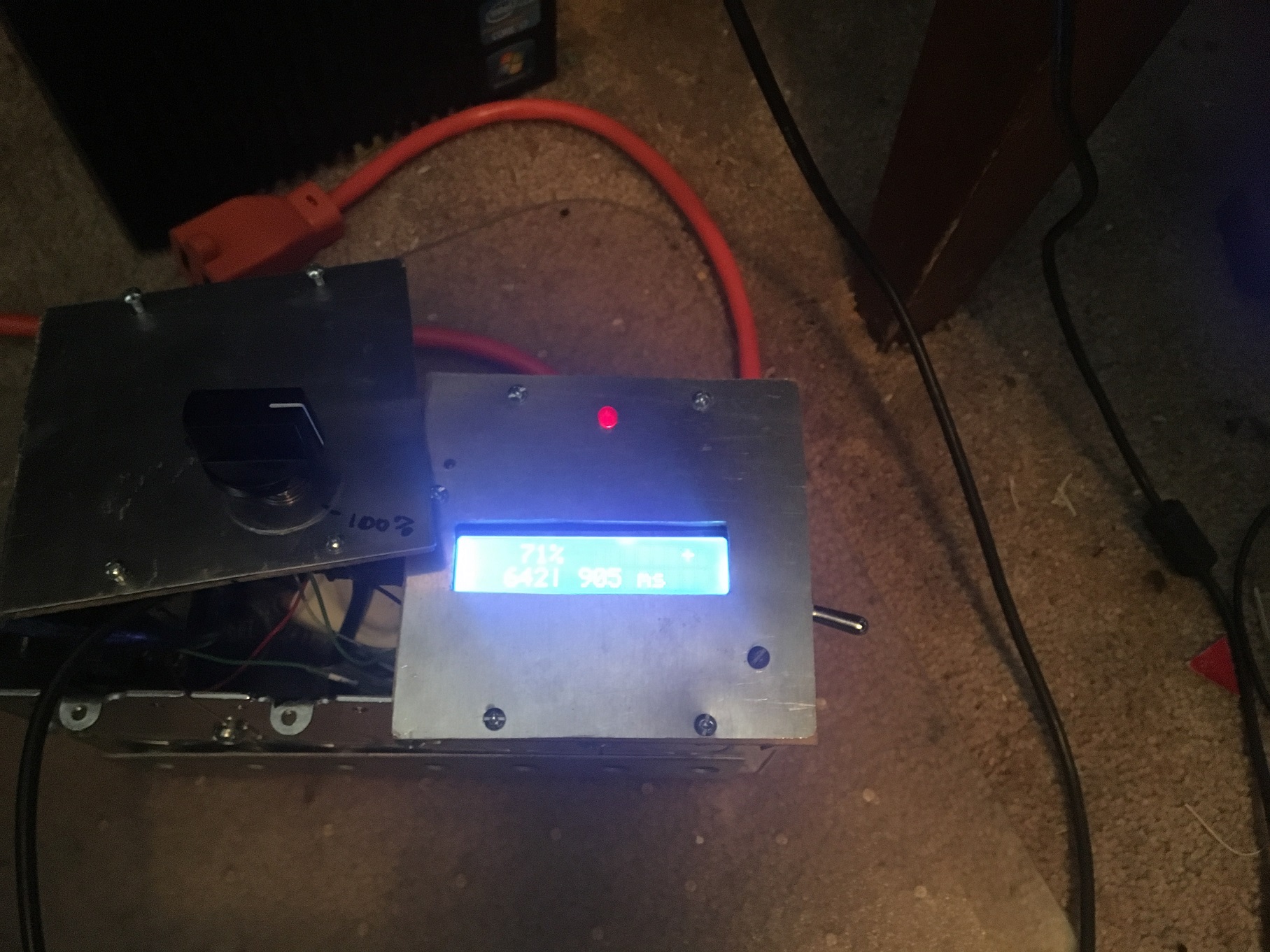
Lastly, it would write the duty cycle percentage, duty cycle and the total
period in milliseconds, so the user could see what the system was set to.
-
The final program: DutyCycle2.0
-
Once the LED to flashed at the correct percentage of the total cycle time,
I connected a second digital output lead to an SSR, to allow it to
control AC power
-
This required a small addition to the program so a second digital output, for
the SSR, would mirror the LED output.
-
Once this was operational, I decided I could add code to the setup section, to allow setting the period that would constitute a full cycle. I used the same POT input to be used to set the cycle time. It was set so it would loop for 2.5 seconds during setup, so it could read this value for setting the period time. I also set it so the 2.5 seconds would reset if the POT input changed, so the user wasn't rushed in setting the cycle time.
- At this point, I tested with a lamp. Seeing if it would turn the lamp on
and off.
It didn't. The light wouldn't turn on at all. Turns out, the digital
output from the Arduino wouldn't drive the SSR. So I added a CMOS buffer
element. Being I didn't have a buffer IC, but did have an hex inverter, I
drove the signal into one of the inverters on the chip, taking the output
through another inverter, to get to the same, slightly amplified "on/off" signal, and
connected that output to the SSR DC input.
- It still didn't work - this time the lamp stayed on. I thought it was
possible the output of the CMOS inverter wasn't bleeding enough voltage away
during the "off" periods to turn it back off. So, I experimented with drop
down resistors (resisters connected to the input, draining excess voltage to
ground). 10K wasn't enough resistance, keeping the lamp off the whole time.
When I tried a 500K ohm resistor, it worked like a charm. The lamp turned on and off in sync with the LED.
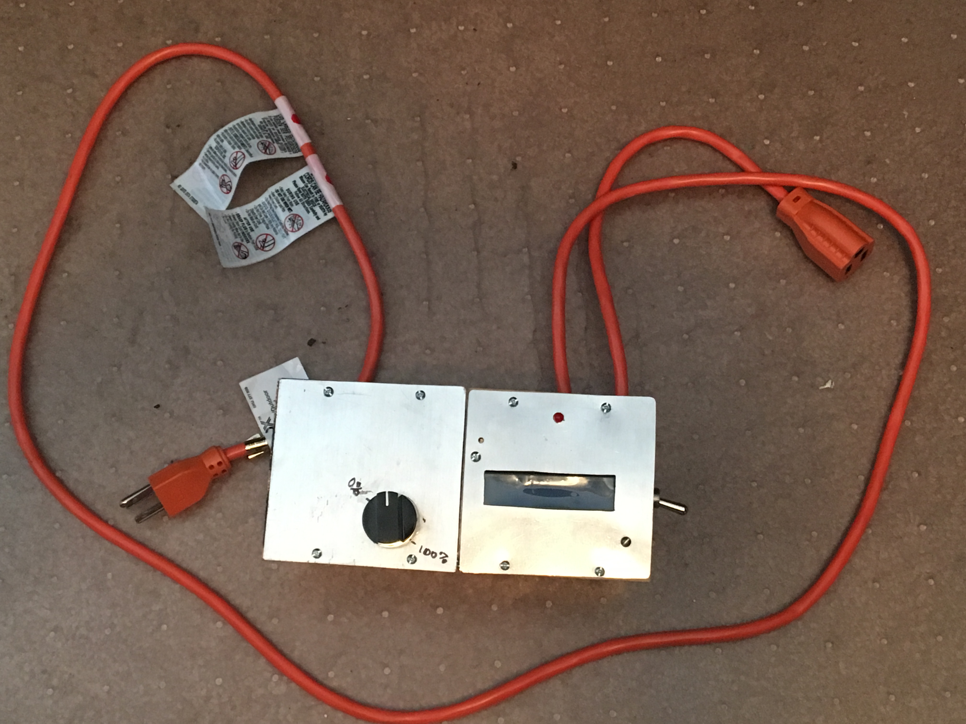
- While the proof of concept now working, it was basically a breadboarded set of wires and components. I needed to house it in a box.
I am too cheap to buy an off the shelf "pro" style electronics box you would pick up at an electronics supply store, so I figured I'd use electrical switch box, similar to what house a wall light switch.
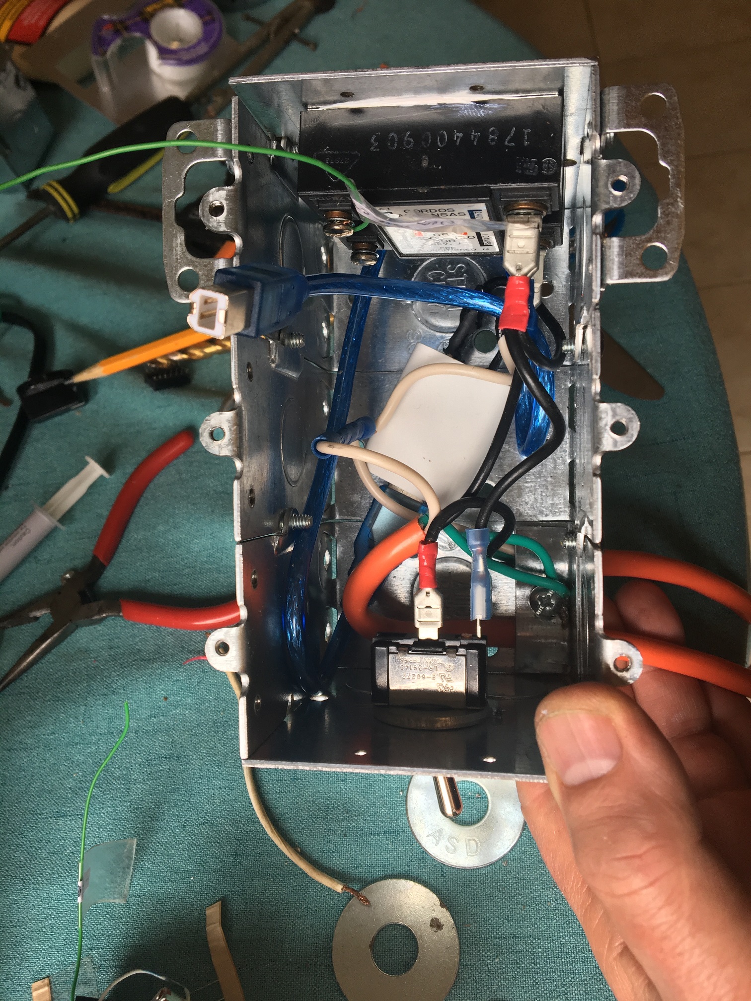
I had a few components I knew I'd have to fit into it. The Arduino, the LCD display, a small board I used for my wiring connections, resistors, and inverter CMOS chip, not to mention the USB charger and the inside portions of the on off switch and POT.
I settled on using a gangable, deep well switch box from Home Depot. These have the advantage they can be "ganged" together to be two, three, or even four together, as one box. I'd have to make a custom top cover, but the customizable interior volume was not only something I found appealing, but later, found it was critical. They had the advantage of having knockout holes to allow AC wiring to both enter the box, but clamped into place.
-
I decided on using a portion of a 15 foot extension cord, a 16/3 variety, to both lead AC power into the box with the switch power coming out as the recepticle end. Since most of the middle would be used, I could take a one foot section out of that part to use for miscellanous AC wiring within the box.
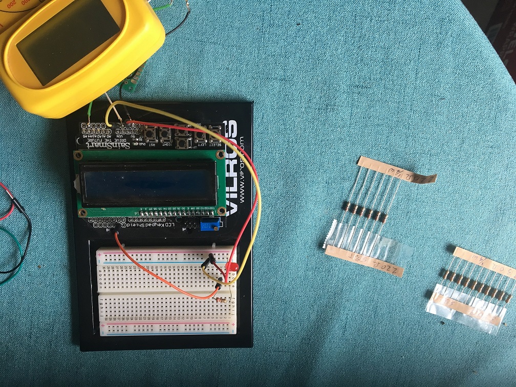
- Before I started putting things into boxes, I had a few small prototyping
circuit boards I could solder my components to. The Arduino LCD shield was
designed to plug into the Arduino, but the prototyping board I chose would
need to be attached, via small machine screws and bolts, to the bottom of the
Arduino/LCD combination and connected via wires.
I soldered my CMOS inverter (actually an IC socket for the IC), resistors, and wiring to the prototyping board and connected leads to the Arduino, LED, and SSR. I was careful to label the wires, so I didn't mistakenly solder a wire to the wrong spot.
-
Each time I moved a connection from the breadboard setup to the prototype
board and soldered it in, I retested to make sure everything still worked.
This caught some errors early, given trying to debug the entire system in one
go would have been a nightmare scenario.
-
When I added the AC switch to the system, the Arduino started acting very
flaky - trying to come on every second or so, even with the switch off. I realized I'd used a "lighted" SPST switch, which allowed just enough juice to flow through, powering it's internal LED, to almost get the Arduino to come up. I had to change to a simple unlit toggle SPST switch. It worked fine after that.
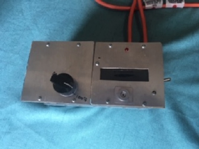
- Once the system was soldered together I got a thin sheet of aluminum to
make a cover with. I cut out a space out of it for the display and LED. I also used a very thin sheet of wood (luan thin, maybe 1/8th inch) and made a similar opening. The aluminum didn't have enough strength for a cover, so adding the thin layer of wood allowed for something more structurally sound. I attached the LCD/Arduino/protoboard to the cover, in the appropriate spot, using machine screws and nuts.
-
I then started figuring out how it would fit into the box. This is where the ganged switch boxes expandability proved advantageous. What I thought might fit in two, turned not into three, but four ganged switch boxes. I had underestimated the amount of space the SSR and the USB charger would take.
-
Because I'd grossly underestimated the space needed, I had to make a second
cover to attach the second half of the box. I drilled a hole in this cover the
POT handle to come through.
I later realized it an advantage to two covers. I could remove the right
hand cover for re-programming the Arduino without risk of damaging the wiring or components. This came in handy later in actual practice.
-
The SSR needed to be bolted to the left side of the box, including some heat
sink paste, so the side of the box would act as a heat sink. The SSR was
unlikely to carry enough current for the heat to become a problem, but better
safe than sorry.
- Once everything was in the box, but before the lid was closed, I again
tested. It worked fine. When I attached the lid, it not only didn't work
properly, the Arduino didn't come on.
- I realized the POT was too close to the side of the box and a lead was shorting out against the metal box housing. I drilled another hole to move the POT away from the wall and everything worked fine when it was reclosed. You'll notice there is a large washer where the POT comes through the lid. That hides the second hole.
-
I rewrote part of the program driving controller. The original
program used "delay" statements to time the on and off periods, meaning it
couldn't read the POT during the time delay. I decided to program it more the way it's described above. The old program I refer to as DutyCycle. The reworked program I called DutyCycle2.0
One thing I started taking into
account was the amount of processing time it took to cycle through the loop.
Turns out it usually maxed out at about 150 milliseconds, averaging about 115
ms. Long in
computer time but Arduinos are very low powered computers. I used 130
ms as the typical loop time. This meant, at the point of checking the time,
if time remaining in the current state (either on or off) measured less than
the loop time, the state change wouldn't happen at the correct time. I changed
it so if the
time remaining was less than loop time, it would delay for the remaining time
then change the state (if appropriate).
-
Once this was done and it was confirmed it still worked, I drilled a small
hole over the reset switch, so I'd be able to trigger a reset without turning
the power off and on again. Again, I misgauged the position, so ended up
drilling a second hole. You'll see an elaborate bit of covering at the hole -
it's not to be fancy, but to hide the unused hole.
Design Elements
Mistakes and Pitfalls
I made a ton of mistakes in this process. While I tend to have a good idea
what I'm going for, I tend to wing it when contructing physical things. This
means I have to re-engineer things frequently.
Switch issues: I had put in the lighted switch before I found it leaked too much voltage.
This means I had to redo the side of the box it was inserted into. Twice. At
first, it was too high, meaning the LCD/Arduino/protoboard hit it before being
seated. So I re did it, only to find the voltage leak problem. Fortunately,
because I was gauging these together, I had six extra gang box sides, being
only the outside two were used in the final product and the others were
extras. The first two holes for the switch were rectangular, meaning a pain in
the rear to cut out. The last was a simple hole, which I drilled.
Wire length issues:
I ran into the issue where my wires, both the 24
gauge electronics wiring, and the 16 gauge AC wiring were too short. Some of
these I simply replace. For many of the wires already soldered in, I snipped
and soldered an extension in the middle, with heat shrink tubbing to cover the
solder spots.
While some of this was poor planning, some was indirect poor planning -
induced when I had to expand the box so things that were long enough, no longer
reached. I wired the protoboard to the Arduino before attaching it
being it would have been extremely difficult to solder after attachment,
which meant some didn't reach or were awkward. A few solder joints broke
during the attachment process.
Programming Issues: It has been a LONG time since I've programmed in
c, the language typically used in Arduino sketches. This lead to a number of
traps, one of which was in type conversion. I had a couple of data overruns in
arrays, leading to strange behavior.
One issue I cannot take credit for, constantly coming up was
Arduino compiler issues. At one point, I had an unused variable use, which was
fine until I tried to delete or comment it out. The compiler would crash. If I
copied all the code to a new project, then it would work. The exact same code
crashed the compiler in one, but didn't in the second. I suspect if I knew how
to force a complete build this would have solved the problem.
General Spatial issues: I had a tendency of underestimated space
needs, positioning holes or elements in positions where they would occupy the
same space as other elements, once fitted together, and had a hard time
estimating where exterior openings would need to match up with internal
elements.
|